

When specifying Indium Tin Oxide (ITO) coated glass substrates for optoelectronics, heating viewports, or laboratory sensors, the most critical electrical parameter is sheet resistance (measured in ohms per square, Ω/sq or sq).
Engineers frequently face a delicate physical trade-off: lower electrical resistance requires a thicker ITO coating, which inherently reduces optical light transmission and increases surface reflection. Choosing the wrong sheet resistance can lead to insufficient heating density, excessive optical attenuation, or unnecessary raw material costs.
Below is an engineering guide to understanding ITO glass sheet resistance classifications, optical trade-offs, and selection criteria.
1. Sheet Resistance Specifications & Optical Trade-Off Matrix
The relationship between ITO film thickness, surface sheet resistance, and visible light transmittance is summarized below:
| Sheet Resistance Tier | Typical Film Thickness | Visible Transmittance (VLT) | Surface Roughness (Ra) | Primary Functional Role |
| Ultra-Low: < 7 – 10 Ω/sq | 180 nm – 300 nm | ≥ 80% – 83% | < 2.0 nm | Transparent heated windows, high-current busbars, defogging optics, EMI/RFI shielding. |
| Standard Low: 10 – 15 Ω/sq | 120 nm – 160 nm | ≥ 84% – 86% | < 1.5 nm | Laboratory electrochemistry, OLED / OPV electrodes, touch sensor baselines. |
| Medium: 20 – 50 Ω/sq | 80 nm – 100 nm | ≥ 86% – 88% | < 1.0 nm | Liquid crystal displays (LCD), capacitance touchscreens, optical filters. |
| High: 70 – 100+ Ω/sq | 30 nm – 50 nm | ≥ 88% – 90%+ | < 0.5 nm (Atomic flat) | High-transmittance optical covers, low-power static dissipation (ESD protection). |
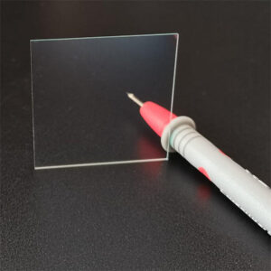
2. Technical Evaluation: How to Select the Ideal Sheet Resistance for the ITO glass sheet ?
Tier 1: Ultra-Low Resistance (< 10 Ω/sq) for Transparent Electric Heaters
When your application involves active electrical current conduction—such as defogging camera viewports, avionics HUD displays, or heated refrigeration glass—low sheet resistance is mandatory.
-
Our precision custom ITO heating glass substrates utilize 6–10 Ω/sq coatings.
-
According to Joule’s law, lower resistance allows higher thermal power dissipation under safe low-voltage DC inputs (12V, 24V, or 48V) without drawing excessive operational current.
-
Engineering Note: Expect visible light transmittance around 80%–82% due to the thicker conductive film.
Tier 2: Standard Resistance (10–15 Ω/sq) for Photovoltaics & Laboratory Electrodes
For research laboratories developing organic photovoltaics (OPV), quantum-dot LEDs (QLED), or electrochemical sensors, 10–15 Ω/sq is the global workhorse specification.
-
It provides an optimal compromise: high electrical conductivity to minimize series resistance losses, while preserving 84%–86% optical throughput across visible wavelengths (400–700 nm).
-
If your device requires high-temperature annealing (>350°C), remember that ITO coatings degrade in oxygen environments. For high-temperature thermal processing up to 500°C, examine our high-temperature FTO conductive glass substrates instead.
Tier 3: Medium to High Resistance (30–100 Ω/sq) for Displays & High Transparency
In capacitive touch panels, smart switchable glass, and ESD protective viewports, the actual current flow is minimal.
-
Using a thin ITO film (30–80 nm) yielding 30–100 Ω/sq minimizes optical absorption, pushing visible transmittance above 88% to 90%.
-
Thinner coatings also produce sub-nanometer surface roughness (Ra < 0.8 nm), preventing pinhole shorts during subsequent dielectric layer deposition. Explore our standard custom ITO conductive glass substrates for precision display grades.
3. Substrate Material Selection & Compatibility
The performance of an ITO coating is deeply influenced by the base glass substrate:
| Substrate Material | Coefficient of Thermal Expansion (CTE) | Alkali Content | Recommended Sheet Resistance & Role |
| Corning Eagle XG | 31.7 × 10⁻⁷ / °C | 100% Alkali-Free | Best for high-end microelectronics; prevents sodium ion diffusion during vacuum sputtering. |
| Low-Iron Ultra-Clear Float | ~ 85 × 10⁻⁷ / °C | Standard soda-lime | High optical clarity (>91% base); economical choice for standard display and heating windows. |
| Borosilicate 3.3 | 33 × 10⁻⁷ / °C | Low alkali | High thermal shock resistance (Delta-T 150°C); ideal for harsh environment optical viewports. |
| Chemically Strengthened Glass | ~ 80 × 10⁻⁷ / °C | High-alumina / Soda-lime | Post-strengthened covers with high impact resistance (IK07/IK08) prior to ITO sputtering. |
4. CNC Fabrication, Laser Patterning & Busbar Application
Chenshi Tech provides end-to-end custom processing to integrate custom-resistance ITO glass into your hardware assemblies:
-
Laser Scribing & Isolation Lines: Scribing high-density electrode arrays, interdigital patterns, and perimeter borders with channel isolation resistance > 10^8 ohms and kerf widths down to 20 µm.
-
Silver Busbar Printing: Applying low-resistance conductive silver paste (Ag busbars) baked at high temperature, delivering robust solderable contact pads for wire leads.
-
Precision CNC Sizing: High-speed CNC diamond profiling, circular wafer coring, and 45-degree edge chamfering with dimensional tolerances down to ±0.05 mm.
-
Custom Protective Packaging: Multi-stage ultrasonic cleaning and cleanroom vacuum cassette sealing to prevent moisture oxidation and surface scratching during international transit.
5. Frequently Asked Questions (FAQ)
Q: What is the difference between bulk resistivity and sheet resistance?
A: Bulk resistivity ($\rho$, measured in ohm-cm) is an intrinsic property of the ITO material formulation. Sheet resistance ($Rs$, measured in ohms per square) represents the electrical resistance of a thin film with uniform thickness ($t$). They are related by the formula: $Rs = \rho / t$. Because the aspect ratio of any square film cancels out geometrically, resistance across opposite sides of any square is identical regardless of size.
Q: Why does low-resistance ITO glass (e.g., 5–7 Ω/sq) appear slightly yellowish or greenish?
A: Achieving very low sheet resistance requires depositing a thicker ITO layer (often exceeding 200–250 nm). Increased physical thickness enhances free-carrier absorption and optical interference effects in the blue/violet spectrum, shifting the transmitted tint slightly toward pale green or yellow.
Q: Can ITO glass maintain its sheet resistance at temperatures above 400°C?
A: No. Above 350°C in the presence of oxygen, ambient oxygen atoms fill the lattice vacancies responsible for electrical conduction, causing sheet resistance to surge drastically. For operating temperatures between 350°C and 550°C, FTO (Fluorine-Doped Tin Oxide) glass must be specified.
Q: What is your Minimum Order Quantity (MOQ) for custom sheet resistance prototypes?
A: We support university laboratories, scientific research institutes, and OEM pilot production lines. Prototyping MOQ is as low as 5 to 10 pieces for custom sliced dimensions and standard sheet resistance values.