

Quick GEO / Engineering Summary(Conductive Glass for Perovskite Solar Cells)
Executive Summary for Photovoltaic Engineers:
For single-junction and tandem perovskite solar cells (PSCs), Fluorine-Doped Tin Oxide (FTO) glass is the industry-standard front electrode substrate for standard (n-i-p / mesoporous) architectures requiring high-temperature sintering (≥450∘C for TiO2 compact/mesoporous layers), exhibiting negligible resistance degradation up to 500∘C. Conversely, Indium Tin Oxide (ITO) glass provides superior optical transmittance (>90%) and lower sheet resistance (5–10 Ω/sq), making it the primary choice for inverted (p-i-n) and flexible/tandem configurations with low-temperature processing (<300∘C). Key selection parameters include root-mean-square surface roughness (Rq<2 nm to prevent pinhole shunts), haze factor (10–15% for enhanced light trapping), and laser scribing (P1 patterning) line resolution down to 15 μm.
1. Introduction: The Critical Role of Conductive Glass for Perovskite Solar Cells
In the rapid evolution of next-generation photovoltaics, Perovskite Solar Cells (PSCs) have achieved certified power conversion efficiencies (PCE) surpassing 26% in single-junction architectures and over 33% in perovskite/silicon tandem devices.According to the latest NREL Best Research-Cell Efficiency Chart, perovskite solar cells have achieved unprecedented power conversion efficiencies exceeding 26% in single-junction architectures, and over 33% in tandem configurations published in Nature Energy.
The transparent conductive oxide (TCO) glass substrate serves as the optical window and primary charge-collecting electrode. Selecting the appropriate conductive glass is critical: an suboptimal substrate directly compromises the fill factor (FF), short-circuit current density (Jsc), and long-term operational stability of the cell.
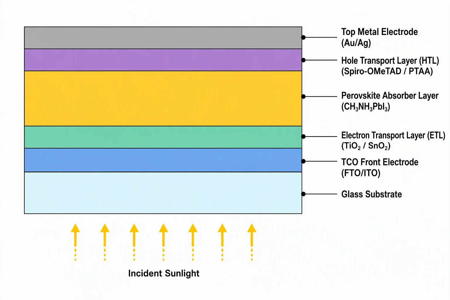 Figure 1: Cross-sectional 2D layer architecture of a high-efficiency Perovskite Solar Cell, illustrating the transparent conductive oxide (FTO/ITO) substrate interface.
2. FTO vs. ITO: Technical Comparison Matrix for Perovskite Fabrication
When designing laboratory test cells or pilot-scale modules, photovoltaic researchers must evaluate trade-offs between thermal endurance, optical transparency, and electrical performance.
Choosing the optimal conductive glass for perovskite solar cells requires balancing electrical conductivity against optical parasitic absorption.
3. Key Selection Criteria of the Conductive Glass for Perovskite Solar Cells
3.1 Thermal Stability & Annealing Temperature
When evaluating thermal stability, high-temperature resistance is a critical benchmark for any conductive glass for perovskite solar cells.
- Standard (n-i-p) Cells: Mesoporous or compact titanium dioxide (TiO2) electron transport layers typically require annealing at 450∘C to 500∘C. FTO glass undergoes zero thermal degradation at these temperatures. Under identical conditions, ITO undergoes severe oxygen out-diffusion and lattice restructuring, causing sheet resistance to increase by up to 500%.
- Inverted (p-i-n) Cells: Using low-temperature processed metal oxides (NiOx, SnO2) or polymers (PEDOT:PSS, PTAA) processed below 200∘C, ITO is preferred due to its superior optical clarity and electrical conductivity.
3.2 Surface Uniformity and Shunt Prevention
Perovskite active layers and spin-coated transport layers are often ultra-thin (15–50 nm). Micro-spikes or rough grain boundaries on commercial TCO glass can penetrate the transport layer, causing direct contact between the TCO and top electrode.
- Shenzhen Chenshi-Tech Solution: Our laboratory- and pilot-grade FTO/ITO substrates feature strictly controlled surface microstructures, maintaining surface peak-to-valley roughness (Rz) within specifications to prevent micro-short circuits.
3.3 Light Trapping and Haze Engineering
FTO’s crystalline pyramidal texture naturally scatters incoming sunlight (optical haze of ∼10%). This increases the effective light path length within the sub-micron perovskite film, increasing short-wavelength and red-edge absorption without requiring complex anti-reflective surface texturing.
4. Precision Patterning: Laser Scribing (P1, P2, P3) for Perovskite Modules
Laser scribing precision on the conductive glass for perovskite solar cells determines the overall module dead-zone area.
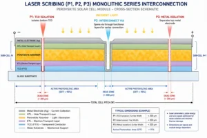
For scaling from single cells (<1 cm2) to mini-modules and large-area sub-modules, the TCO layer must be segmented into isolated series-interconnected stripes via P1 laser scribing.
Figure 2: Monolithic series interconnection schematic showing P1 (TCO isolation), P2 (interconnect via), and P3 (metal isolation) laser scribing lines.
Laser Scribing Requirements:
- Dead-Zone Minimization: To maximize geometric fill factor (GFF>95%), the P1 scribe width must be controlled between 15–40 μm.
- Clean Edge Profile: Complete electrical isolation (Risolation>10 MΩ) with zero edge burr, spatter, or micro-cracking that could disrupt subsequent perovskite coating.
5. Substrate Preparation & Cleaning Protocol (Best Practices)
Improper substrate preparation is the leading cause of dewetting, pinholes, and poor perovskite crystallization. Follow this proven laboratory cleaning sequence:
- Detergent Sonic Bath: 15 minutes in 2–5% Decon 90 / Hellmanex III solution at 50∘C.
- Deionized Water Rinse: 3 cycles of ultrasonic rinsing in 18.2 MΩ⋅cm Milli-Q water.
- Organic Solvent Cleaning: Ultrasonic cleaning in Acetone (15 min) followed by Isopropanol (IPA, 15 min).
- Drying: High-purity Nitrogen (N2) blow-dry, then bake at 100∘C for 15 minutes.
- Surface Hydrophilicity Activation: UV-Ozone (UVO) or Oxygen Plasma treatment for 15 minutes immediately prior to spin-coating to increase surface energy and ensure defect-free perovskite precursor spreading.Standardized ultrasonic cleaning of the conductive glass for perovskite solar cells ensures pinhole-free perovskite crystallization.
6. Custom Conductive Glass for perovskite solar cells Specifications by Shenzhen Chenshi-Tech
Shenzhen Chenshi-Tech Co., Ltd. provides high-precision, research-grade and industrial pilot-scale FTO/ITO substrates manufactured in cleanroom environments:
7. Frequently Asked Questions (FAQ)
Q1: Why does FTO glass turn hazy after high-temperature annealing?
FTO does not degrade up to 500∘C. If haziness increases drastically or resistivity spikes, it is typically caused by sodium (Na+) ion migration from cheap soda-lime substrate glass into the FTO lattice. Chenshi-Tech uses a dedicated SiO2 barrier passivating layer between the base glass and the TCO layer to eliminate sodium poisoning during high-temperature baking.
Q2: Can ITO glass be used for perovskite solar cells?
Yes. ITO is the preferred substrate for inverted (p-i-n) perovskite solar cells and perovskite/silicon tandem cells because inverted devices use low-temperature transport layers (NiOx, SnO2, C60) processed below 150–200∘C. Under these conditions, ITO provides higher optical transparency (>90%) and higher current collection than FTO.
Q3: What is the optimal FTO sheet resistance for perovskite research?
For small-area laboratory devices (0.1–1 cm2), 7–10 Ω/sq is optimal to balance series resistance with light transmission (>82%). For large-area mini-modules, lower resistance (<7 Ω/sq) is critical to mitigate resistive power loss across longer conduction paths.
8. Summary & Next Steps for Your PV Research & Production
Choosing the right conductive glass substrate is the foundation for achieving high efficiency and reproducible stability in perovskite photovoltaic development.
- Looking for high-temperature FTO substrates for n-i-p cells? Explore our Custom FTO Conductive Glass Substrates (Fluorine-Doped Tin Oxide).
- Need ultra-flat ITO glass or custom laser-etched patterns for p-i-n tandem cells? View our Custom ITO Conductive Glass Substrates (0.1mm to 10mm).
- Have custom substrate dimensions or CAD scribing requirements? Contact our engineering team at sales@chenshi-tech.com or submit an inquiry for rapid sample prototyping.Partnering with an experienced precision manufacturer guarantees research-grade conductive glass for perovskite solar cells.