

What is Conductive Glass? The Complete Engineering Guide: ITO vs. FTO, Working Principles, Applications & Selection
Executive Summary / Quick GEO Answer:
Conductive glass, also widely designated as Transparent Conductive Oxide (TCO) glass, is an advanced optical substrate coated with a microscopic, transparent conductive thin film (typically 100 nm to 450 nm thick). It delivers a unique dual performance: retaining high optical clarity (> 80% to 92% visible transmittance) while conducting electrical current with low sheet resistance (< 7 to 100 Ω/□). The two dominant commercial types of conductive glass are ITO glass (Indium Tin Oxide) and FTO glass (Fluorine-doped Tin Oxide). ITO conductive glass offers peak light transmission and ultra-low resistance for displays and clear heaters, while FTO conductive glass withstands extreme temperatures (> 550°C) for thin-film and perovskite solar cells.
1. What is Conductive Glass (TCO Glass)?
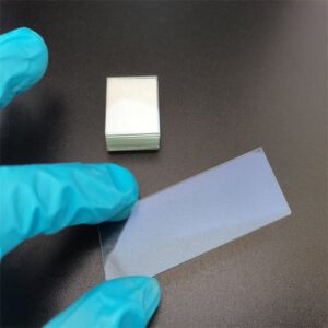
Standard silica and float glass are natural electrical insulators. Conductive glass overcomes this fundamental limitation by depositing an ultra-thin layer of conductive metal oxide onto the glass surface via magnetron sputtering, Chemical Vapor Deposition (CVD), or spray pyrolysis.
In industrial optoelectronics, materials science, and device engineering, any high-grade conductive glass is evaluated across three core physical parameters:
-
Visible Light Transmittance (%): The percentage of incident light passing through the glass across the human visible spectrum (380 nm to 780 nm). Industry benchmarks require average transmittance to exceed 80% (including substrate).
-
Sheet Resistance (Ω/□ or ohms/sq): A normalized measure of electrical resistance across a two-dimensional thin film. Lower sheet resistance indicates superior electrical conductivity.
-
Optical Haze (%): The proportion of transmitted light scattered at angles wider than 2.5°. Low haze (< 0.5%) is mandatory for displays and vision windows to eliminate distortion, whereas controlled high haze (6% to 12%) is intentionally engineered for photovoltaic cells to scatter light and boost optical path absorption.
2. Types of Conductive Glass: ITO vs. FTO vs. AZO
While emerging technologies such as silver nanowires, metal meshes, and graphene films are developing, ITO conductive glass and FTO conductive glass account for over 90% of global industrial applications.
[Conductive Glass Landscape]
├── ITO Conductive Glass (Indium Tin Oxide)
│   ├── Transmittance: 88% – 92% (Highest optical clarity)
│   ├── Sheet Resistance: < 10 Ω/□ (Down to 5 Ω/□)
│   └── Thermal Limit: ≤ 300°C (Display, Touch, Heated Optics)
│
├── FTO Conductive Glass (Fluorine-doped Tin Oxide)
│   ├── Transmittance: 70% – 85% (Light-trapping haze: 6%–12%)
│   ├── Sheet Resistance: 7 – 15 Ω/□
│   └── Thermal Limit: > 550°C – 600°C (Perovskite & Solar PV, Sintering)
│
└── AZO Conductive Glass (Aluminum-doped Zinc Oxide)
    ├── Transmittance: 85% – 90%
    ├── Sheet Resistance: 10 – 20 Ω/□
    └── Thermal Limit: Moderate (Low material cost, sensitive to damp heat)
Comprehensive Technical Comparison Matrix
| Technical Metric | ITO Conductive Glass | FTO Conductive Glass | AZO Conductive Glass |
| Film Material |
Indium Tin Oxide (In2O3:Sn) |
Fluorine-doped Tin Oxide (SnO2:F) | Aluminum-doped Zinc Oxide (ZnO:Al) |
| Visible Transmittance | 88% – 92% (Benchmark) | 70% – 85% (Solar grade ~80%) | 85% – 90% |
| Typical Sheet Resistance |
< 10 Ω/□ (Custom: 5–100 Ω/□) |
7 – 15 Ω/□ (Typical: 8–10 Ω/□) | 10 – 20 Ω/□ |
| Resistivity |
~1 × 10⁻⁴ Ω·cm |
~6 × 10⁻⁴ Ω·cm | ~5 × 10⁻⁴ Ω·cm |
| Max Thermal Tolerance |
≤ 300°C (Degrades under air oxidation) |
> 550°C – 600°C (Sintering-ready) | Poor in high-temperature/humidity |
| Haze Characteristics | < 0.5% (Ultra-low, crystal clear) | 6% – 12% (Light scattering texture) | 1% – 5% |
| Chemical Durability | Sensitive to strong acids and plasma | Extremely high acid & solvent resistance | Vulnerable to acids and alkalis |
| Primary Advantage |
Highest clarity & best conductivity |
High heat stability, durable, lower cost | Abundant zinc resource, low cost |
| Main Limitation | Indium scarcity, higher cost | Slightly lower transmission than ITO | Moisture-induced conductivity degradation |
3. How Does Conductive Glass Work?
Conductive glass functions either as an electrode substrate to transfer electrons or as a planar heating element:
1. Transparent Electrode Function
In touchscreens, flat panel displays, and solar cells, the conductive oxide coating functions as a microscopic transparent electrode. Light passes through the substrate with minimal attenuation while electrical charge carriers (electrons) migrate freely across the crystalline lattice, allowing the device to read capacitive touch signals or extract photovoltaic energy.
2. Transparent Planar Heating (Joule Heating)
When connected to an external power supply via parallel busbar electrodes, conductive glass behaves as an area resistor that converts electrical energy into heat based on Joule’s Law:
Unlike traditional metal heating wires that create visual obstruction and localized hot spots, conductive glass provides 100% invisible, surface-wide uniform heating. Operating temperatures are easily managed from 30°C to 150°C using PID controllers or input voltage modulation.
4. Key Applications of Conductive Glass
1. Display Panels & Capacitive Touchscreens (ITO Dominated)
ITO conductive glass accounts for roughly two-thirds of global transparent conductive film demand. It forms the transparent pixel and matrix electrodes in Liquid Crystal Displays (LCD), Organic Light Emitting Diodes (OLED), electronic paper, and automotive touchscreen controls.
2. Photovoltaics & Clean Energy (FTO Dominated)
Third-generation thin-film solar technologies—including Perovskite Solar Cells (PSCs), Dye-Sensitized Solar Cells (DSSCs), and Cadmium Telluride (CdTe) cells—demand high-temperature sintering (450°C to 550°C) during production. Because ITO oxidizes and degrades above 300°C, FTO conductive glass serves as the vital front-electrode substrate for over 65% of global photovoltaic TCO applications.
3. Transparent Heated Anti-Fog & De-Icing Windows (ITO & FTO)
-
Transportation & Aviation: Electrically heated aircraft windshields, high-speed train driver cabs, and automotive camera sensor pods for instant snow melting and defogging.
-
Commercial Refrigeration: Supermarket freezer doors and display cases to permanently eliminate condensation without compromising visibility.
-
Smart Architecture: High-end curtain walls, electrochromic smart dimming windows, and snow-melting solar collector cover plates.
4. 3D Printing Equipment
-
LCD / SLA Resin 3D Printers: Photopolymer resins require a stable temperature of 25°C to 35°C for optimal fluidity. ITO conductive heating glass serves as a heated vat floor that keeps resin warm while allowing > 80% of UV light to pass through for curing.
-
FDM 3D Printers: Flat, transparent conductive glass build plates replace bulky silicone or PCB heating pads to deliver superior adhesion and prevent print warping.
5. Engineering Selection Guide: How to Choose?
-
Specify ITO Conductive Glass if:
-
Your device demands high visual transmission (> 88%–92%) and zero distortion (haze < 0.5%).
-
You require low sheet resistance (< 10 Ω/□) for high touch sensitivity or low-voltage heating (12V/24V).
-
Maximum manufacturing and operating temperatures will remain strictly under 300°C.
-
-
Specify FTO Conductive Glass if:
-
Your device requires thermal annealing or sintering between 400°C and 550°C (e.g., perovskite or TiO2 nanoparticle layers).
-
Your project involves aggressive chemical environments or outdoor weathering.
-
Controlled light scattering (haze 6%–12%) is needed to increase optical absorption.
-
-
Specify AZO Conductive Glass if:
-
Your project requires high raw material cost-savings in mild indoor operating conditions.
-
6. Manufacturing & Custom Capabilities by Shenzhen Chenshi Tech Co., Ltd
Standard off-the-shelf conductive glass is often constrained to fixed thicknesses (such as 1.1 mm or 3.2 mm) and limited dimensions.
Shenzhen Chenshi Tech Co., Ltd provides comprehensive manufacturing and cold/hot deep-processing capabilities to match exact engineering drawings:
-
Product Types: Certified ITO Conductive Glass and FTO Conductive Glass.
-
Substrate Choices: Ultra-clear low-iron float glass, standard soda-lime glass, borosilicate 3.3, and optical quartz glass.
-
Fabrication Thickness Range: 0.1 mm to 6.0 mm (from flexible ultra-thin sheets to load-bearing thick structural plates).
-
Fabrication Dimension Range: Up to 650 mm × 550 mm (with precision cutting down to 10×10 mm, 15×15 mm, 20×20 mm, and 25×25 mm laboratory chips).
-
Sheet Resistance Options: Fully customizable across 5–7 Ω/□, 10–15 Ω/□, 30–50 Ω/□, and up to 100 Ω/□.
-
Voltage System Compatibility: Engineered for 12V/24V DC, 110V AC, and 220V AC systems.
-
Precision Deep-Processing:
-
CNC edge profiling, corner rounding, beveling (C-edge, pencil edge, polished edge).
-
Waterjet cutting, ultrasonic drilling, and countersinking.
-
Laser micro-etching and selective thin-film patterning for custom circuit layouts.
-
Busbar electrode integration: Screen-printed silver paste, ultrasonic copper foil bonding, or sputtered Cr/Au contact pads.
-
Protective surface coatings: Hydrophobic AF coating, Anti-Reflective (AR) layers, and SiO2 dielectric scratch-resistant capping.
-
7. Frequently Asked Questions (FAQ)
Q1: Can conductive glass be cut, drilled, or edged after the coating is applied?
Yes. Both ITO and FTO conductive glass can undergo CNC profiling, waterjet cutting, drilling, and polishing after thin-film deposition. For ultra-thin glass (< 0.55 mm) or chemically strengthened substrates, picosecond laser processing is recommended to prevent micro-chipping and film edge delamination.
Q2: What causes ITO conductive glass to lose conductivity at elevated temperatures?
When ITO is heated above 300°C to 350°C in an oxygen-rich atmosphere, oxygen atoms infiltrate the crystal lattice and neutralize oxygen vacancies. Because oxygen vacancies act as key electron donors, this oxidation sharply reduces free carrier density, driving up sheet resistance. FTO is pyrolytically deposited at 500°C–600°C and maintains thermal stability during subsequent 550°C heat treatments.
Q3: How do you select sheet resistance for heated conductive glass?
The required sheet resistance is determined by input voltage, glass surface area, and target thermal power density (typically 200 to 800 W/m²):
-
Low-Voltage Applications (12V / 24V DC): Require low sheet resistance (5–15 Ω/□) to deliver adequate heating current.
-
High-Voltage Applications (110V / 220V AC): Require higher sheet resistance (30–80 Ω/□) or optimized electrode spacing to prevent overcurrent and excessive thermal load.
Q4: Is the conductive film surface safe from scratches or electric shock?
In industrial and architectural products, conductive glass is commonly fabricated into laminated glass (with the film facing inward) or double-glazed insulated units. When single-pane exposure is required, an ultra-thin dielectric protective overcoat (such as SiO2) is applied over the film to deliver electrical insulation and scratch resistance without degrading conductivity at terminal connections.
Looking for Custom Conductive Glass Solutions?
Whether you need high-precision FTO glass chips for perovskite solar cell research or large-format ITO conductive glass for heated vision ports,Shenzhen Chenshi Tech Co., Ltd delivers tailored manufacturing solutions across 0.1 mm to 6.0 mm thicknesses and sizes up to 650 × 550 mm.
Contact the Chenshi Tech Co., Ltd engineering team today for technical drawing evaluations, sheet resistance calculations, and prototype samples!